Build Guide
Advanced electronics bundle
Step-by-step wiring guide for the StrongHold Pro using the Intermediate Electronics Bundle together with the Universal CNC Electronics Enclosure (UCEE).
01. Wiring
Follow this chapter if you choose the advanced electronics bundle, which includes the AXBB CNC controller and 2.2Kw Spindle.
In this chapter all the connections from the controller to the machine will be established.
02. AC Mains Wiring Safety disclaimer
Important Safety Disclaimer!
This guide covers the AC wiring for the Universal CNC Electronics Enclosure (UCEE).Working with 230V / 110V AC is extremely dangerous and can cause severe injury or death. This wiring must only be performed by a qualified electrician or an individual with proven electrical experience.
By following this guide, you acknowledge that:
• All wiring must comply with local electrical laws and regulations.
• You assume full responsibility and risk for the installation.
• Rat Rig is not liable for any damage, injury, or loss caused by improper installation.
• You assume full responsibility and risk for the installation.
• Rat Rig is not liable for any damage, injury, or loss caused by improper installation.
If you are not certain you can perform this task safely, do not proceed. Contact a licensed electrician.
Always disconnect power sources before beginning.
03. How to crimp
Ensuring good crimps on 230V/110V circuits is critical for both safety and performance. Crimps provide a secure and stable connection between electrical wires and terminals, essential in preventing loose connections that can lead to overheating, short circuits, or electrical fires. A properly executed crimp ensures low resistance and high conductivity, which is crucial for maintaining the efficiency and reliability of the electrical system.
Warning!
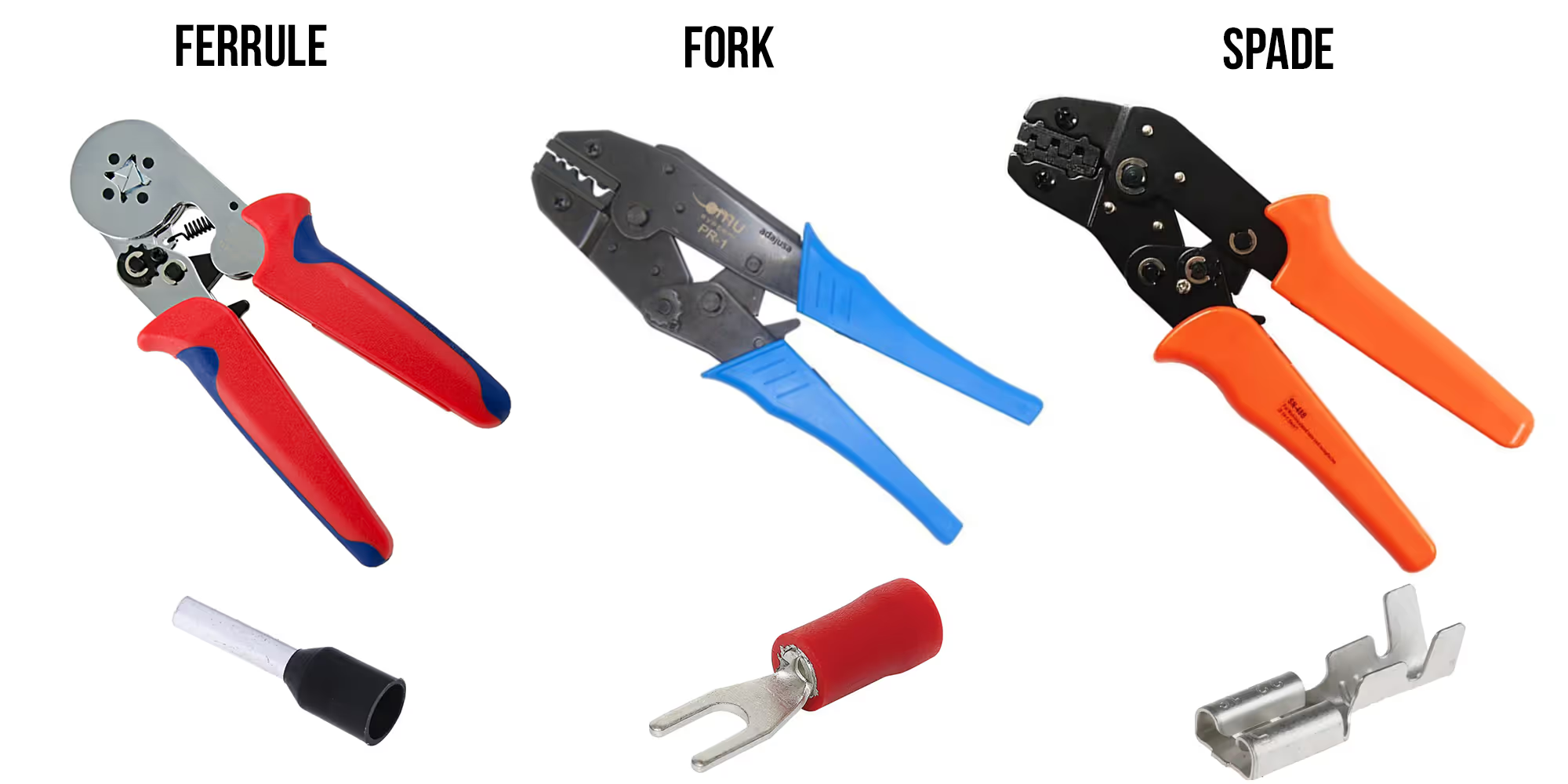
Always use the proper tools for crimping connectors. Poor crimps can damage components, create fire hazards, and pose injury risks. Below are examples of suitable crimping tools, including models that support multiple connector types.
When crimping a spade connector, remember to insert the silicone cover onto the wire before performing the crimp.
Warning!
Never connect the power cord to the IEC inlet until all wiring is complete and the AC cover is installed. Always triple-check connections, as an incorrect wire placement can result in severe damage or injury.
04. Install the mains power wires
Wire the components as shown below. Use ferrules for the PTFix blocks and spade connectors for the IEC inlet and fuse holder.
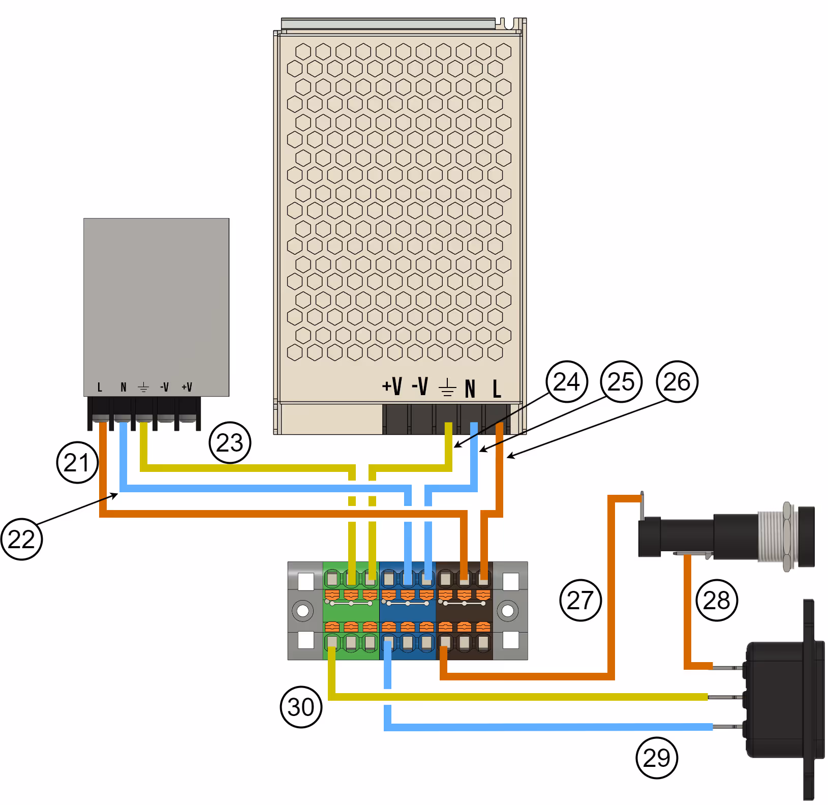
- 280mm - 18AWG Brown (A-Spade, B-Ferrule) (27)
- 100mm - 18AWG Brown (A-Spade, B-Spade) (28)
- 280mm - 18AWG Blue (A-Spade, B-Ferrule) (29)
- 280mm - 18AWG YellowGreen (A-Spade, B-Ferrule) (30)
Note!
After wiring, gently pull each cable to verify that all connectors are properly secured.
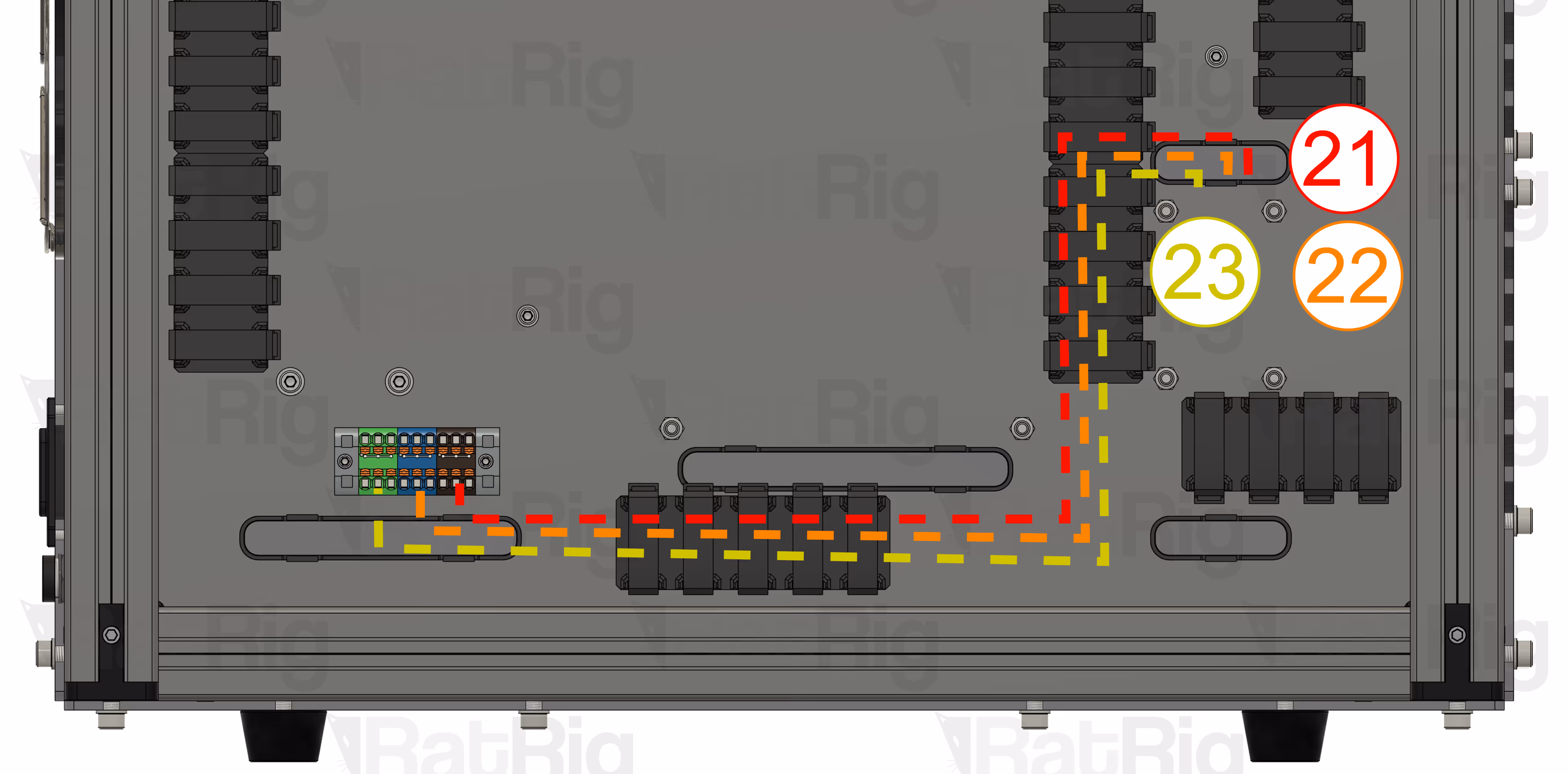
Route wires (21), (22) & (23) as shown:
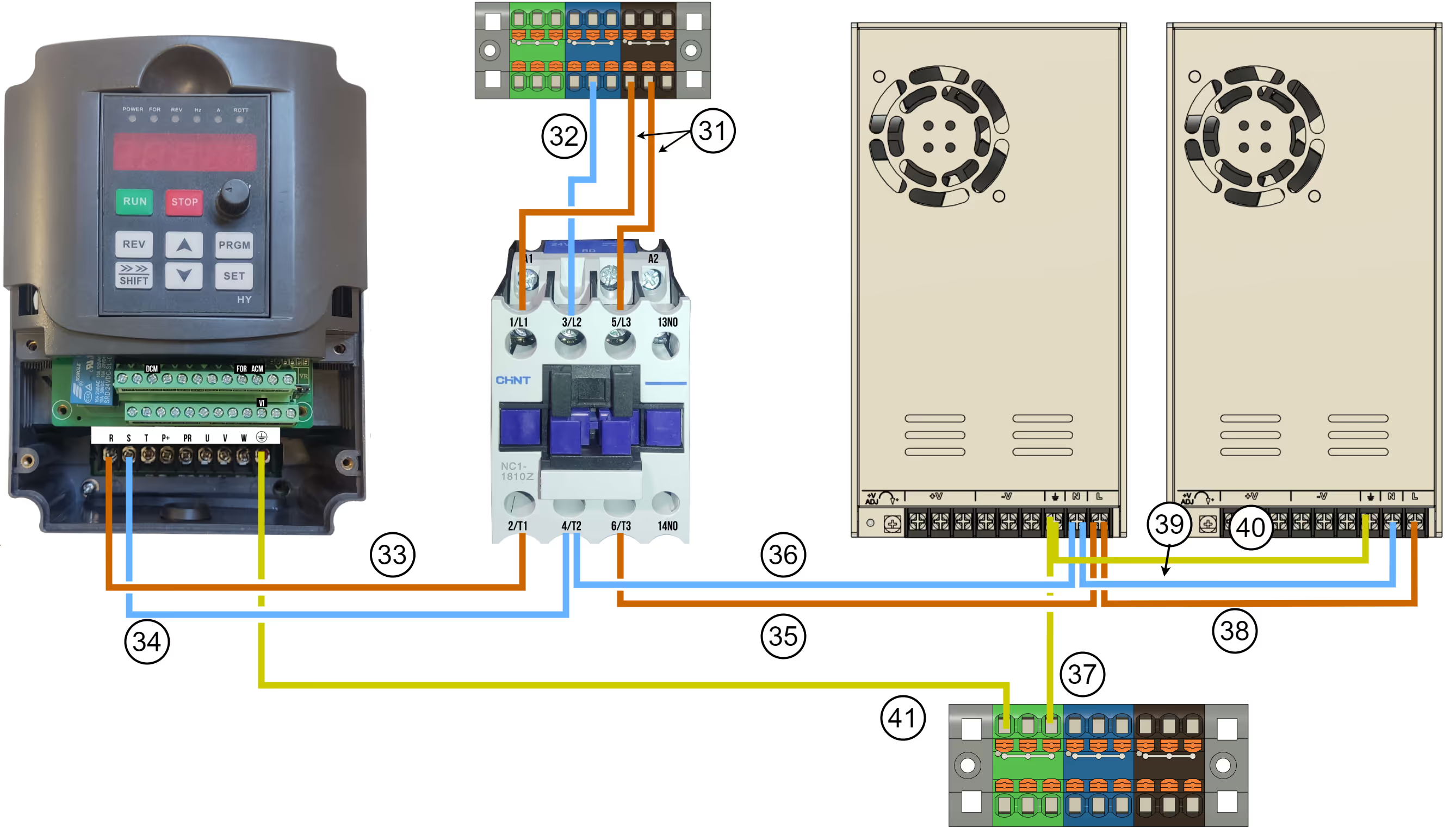
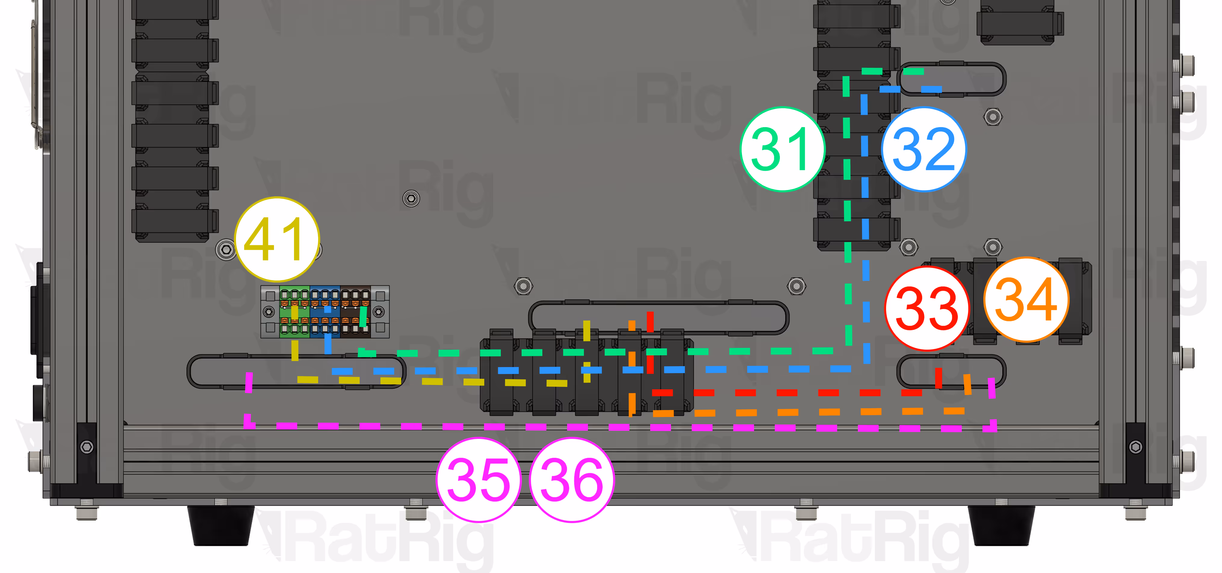
05. Connect the VFD + spindle
Wire the components as shown below, using the fork terminals for the Contactor and VFD, and the ferrules for the PTFix Blocks.
Note!
After wiring, gently pull each cable to verify that all connectors are properly secured.
- (2x) 600mm - 18AWG Brown (A-Fork, B-Ferrule) (31)
- 600mm - 18AWG Blue (A-Fork, B-Ferrule) (32)
- 400mm - 18AWG Brown (A-Fork, B-Fork) (33)
- 400mm - 18AWG Blue (A-Fork, B-Fork) (34)
- 500mm - 18AWG YELLOWGREEN (A-Fork, B-fork) (41)
Route the wires as shown:
Warning!
Before powering on, ensure all connections are secure, properly crimped, and correctly wired according to the diagram. Additionally, verify that the color scheme is followed accurately to maintain consistency and safety.