Intermediate electronics Bundle
Sanity Check
After completing the firmware installation, connect your control device (e.g., a laptop) to the machine. This can be done either through the FluidNC Web UI or via a serial sender such as UGS. The FluidNC Web UI is tailored for this firmware, while UGS is more generic, but the direct USB serial connection provides fast and responsive control. Both options are valid, though we recommend starting with the FluidNC Web UI.
00. Prepare FluidNC
FluidNC is a CNC firmware optimized for the ESP32 controller, developed as the next generation of Grbl_ESP32. It features a web-based UI and supports a wide range of machine types, including multi-tool configurations such as laser + spindle or tool changers.
Before proceeding with this guide, refer to the FluidNC installation wiki for a quick start guide on installing the firmware on your machine:
FluidNC Wiki Page01. Spindle water pump
The water cooling hoses should have been installed on the spindle here. Route them to the desired location for the water tank and trim them to the appropriate length. A simple plastic container filled with distilled water is generally sufficient. However, if you intend to operate the spindle under heavy loads for extended periods, consider using a more effective cooling solution.
- Place the water pump inside the water reservoir and securely connect the hoses.
- Fill the cooling system with distilled water, as regular tap water is not recommended. Tap water can cause mineral buildup, potentially damaging both the water pump and the spindle. It is also recommended to use Algae Prevention solutions to inhibit algae and mold growth in the coolant reservoir. If your environment is cold, consider adding an antifreeze solution to prevent freezing and protect the cooling system.
- Plug the water pump to the mains power and water should start flowing.
- Always ensure that the water pump is turned on before powering the spindle. A helpful tip is to use the relay inside the VFD to control the water pump, ensuring it operates automatically when needed.
02. E-Stop Circuit
Before beginning operation, it is essential to verify that the E-stop (Emergency Stop) circuit is functioning correctly as intended:
- Power Connection: Connect the machine to the main power supply.
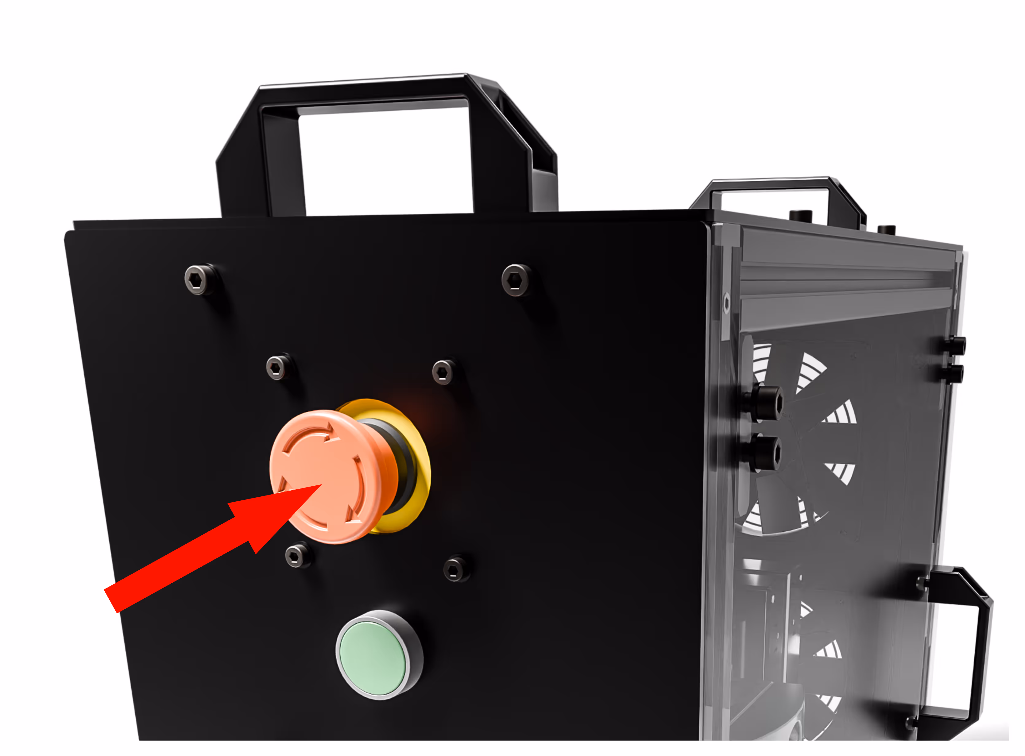
- Releasing the E-stop: Rotate the E-stop button clockwise to release it.
- Starting the Machine: Press the start button. You should hear a distinct "clack" sound, which indicates the contactor is engaging. This is normal.
- Powering On: The Rodent and VFD (Variable Frequency Drive) should power on. Note that the VFD may take a few seconds to fully activate.
- Testing the E-stop: Once both the VFD and Rodent are powered on, press the E-stop button. This should turn them off. It is normal for the VFD to take a few seconds to power down, especially when the spindle is not in motion.Before beginning operation, it is essential to verify that the E-stop (Emergency Stop) circuit is functioning correctly as intended.
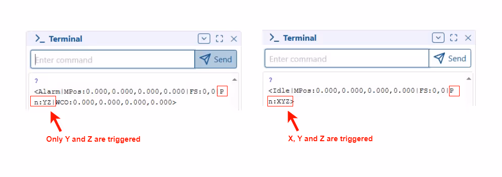
- If the Y endstop is triggered but the firmware reports X or Z as being triggered, this indicates that the endstops are swapped on the control board. Check and correct the connections on the Rodent if necessary.
03. Home Sequence
- Home the machine and verify that all axes move towards their respective endstops.
- Stay near the emergency stop button in case any endstop is misaligned and fails to trigger. This is a recommended safety practice for any CNC machine. While the hardware can generally be trusted, it is important to remain prepared for any unexpected issues during the commissioning phase.
04. Axes Direction
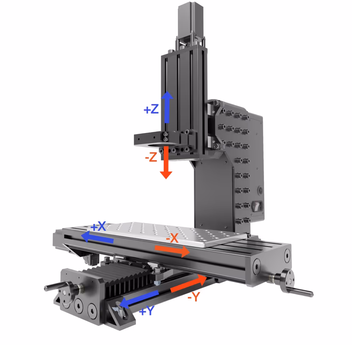
- Select the desired distance and adjust the movement of each axis in small increments.

- The movements should follow the directions indicated in the image below.