CAD
CAD models for all V-Core 4.0 sizes and variants are available via the Rat Rig Fusion online viewer. Choose a variant below to view the CAD model and enable the download button below.
Bill of Materials - BOM
Below you can find the Bill of Materials (BOM) spreadsheet for the V-Core 4.0. Please be aware that the machine size affects the lengths of some components such as extrusions, linear rails, lead screws and wiring. The hardware packs are universal for all sizes.
Official BOM V-Core 4.0Enclosure panels
Click the button below to download the DXF and STEP files for the V-Core 4.0 panels. Please be aware that the design is intended to use 4mm thick polycarbonate panels.
Printed parts
All files are provided in the correct orientation for printing on a standard FDM 3D printer. In general, the printed parts are quite forgiving but are also quite large. If you suffer from drafts and/or poor bed adhesion you may need to use brims/rafts for some parts to prevent warping.
Induvidual STLs are available on GitHub
If you are building the IDEX upgrade, make sure to also download the dedicated IDEX pack, as it includes the additional STLs required for the IDEX toolheads and VAOC.
The following table shows the recommended print settings when printing any of the parts provided.
Print Settings:
- Perimeters
- 4
- Line Width
- 0.45mm
- Layer height
- 0.2 - 0.3 mm
- Infill
- 25%
- Supports
- None
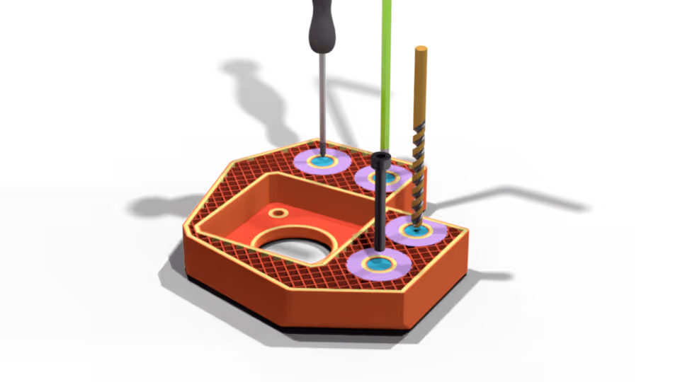
When slicing the files you will notice that some of the holes are covered. This is intentional, to simplify the printing process - those layers are there to trick the slicer into building a bridge there. Once printed those need to be poked out with a screw, screwdriver, Allen key or even a matching size screw.