V-Core 4 Idex Commissioning Guide
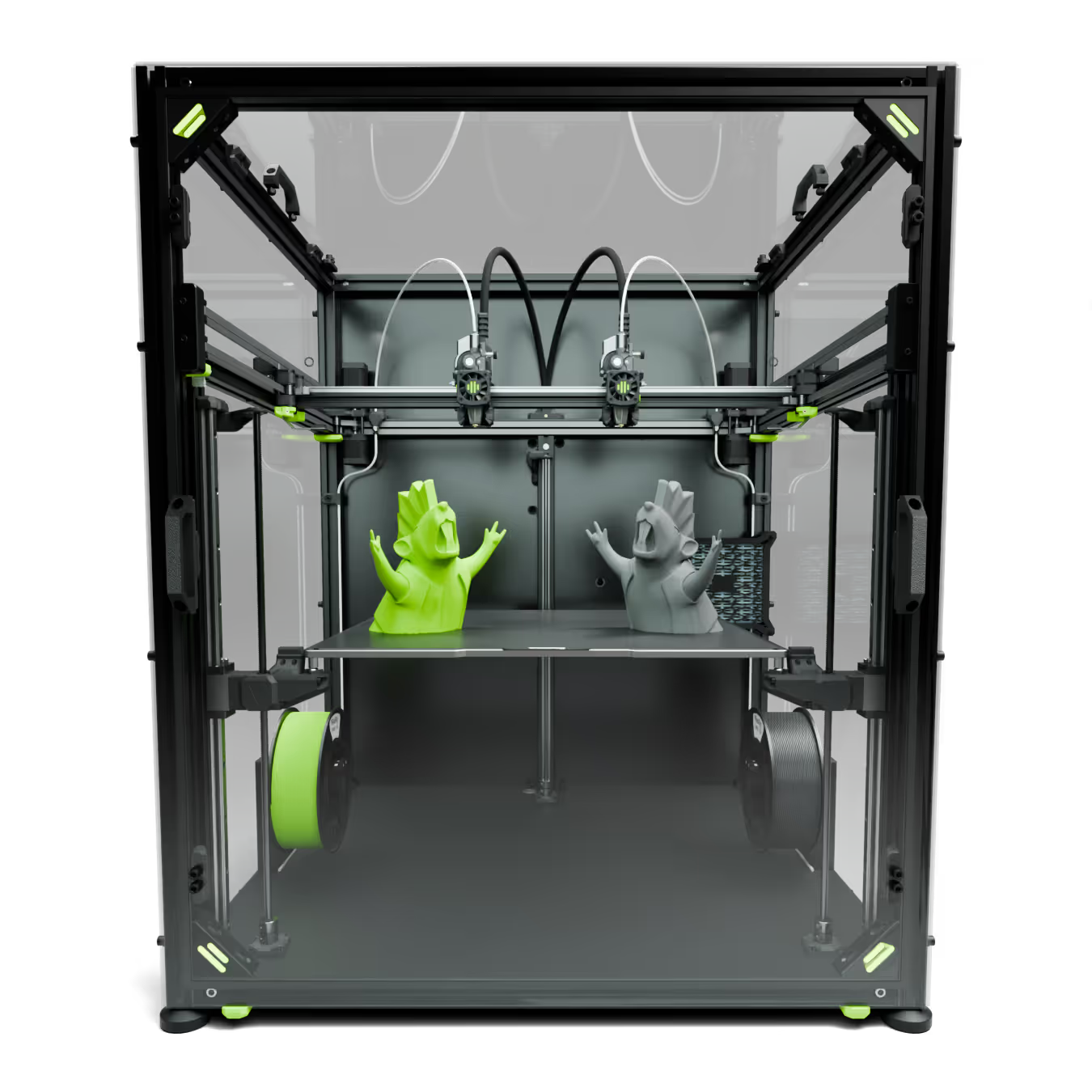
Welcome to the Idex world!
The IDEX machine is very distinct from conventional 3D printers it offers a range of remarkable capabilities while unlocking new possibilities. However, it requires a solid understanding. This guide is designed to support every user on their IDEX journey. This page will cover all aspects of the IDEX setup, from configuration and calibration to slicing, ensuring you have the knowledge and confidence to maximize its potential. We are continually refining the experience, learning from the community to make improvements and enhance usability. If you have any feedback, please don’t hesitate to reach out, your insights are invaluable to us in shaping a better experience for everyone. Do so on our Discord channel, Facebook group or via email. Enjoy the process!
(If you have not finished your mechanical assembly, click the button below)
After completing the mechanical assembly, Let's go!
The buttons below will redirect you to each of the main sections of the IDEX commissioning guide.
⚠️Belt tension
A comprehensive belt tension guide for the IDEX machine is currently being developed, with full consideration given to the sensitivities surrounding this topic. It should be noted that expecting "perfect" input shaping graphs or belt tension graphs may not align with the inherent limitations of the IDEX variant. Due to the nature of this machine, achieving flawless graphs is not feasible.
Configuration
This chapter is specifically intended for the IDEX configuration. It will cover the VAOC configuration and the initial steps for setting up and operating the IDEX machine. We are working on automating this process.
If you are upgrading from a hybrid machine, pre-configured, disable performance mode in the RatOS configurator.
Step 1 - Printer selection
First, navigate to the configurator and then proceed to the setup wizard. In the printer selection menu, choose the IDEX variant that corresponds to the appropriate size of your machine. If you have any custom configurations, such as LEDs, filters, fans, temperature sensors, or other modifications, ensure that you save those settings to a local file, as they will be erased during the IDEX update. To preserve your settings, download your printer.cfg file before proceeding. Please follow the red numbers in sequential order.
Next, click on "Confirm Your Setup," followed by "Review Changes." Accept the changes to allow RatOS to modify your printer configuration to the IDEX setup.
Click the "Confirm and Save" button. The machine will then restart with the new parameters applied.
Step 2 - Configure the Z Endstop and VAOC LED
Navigate to the printer.cfg file and scroll to the bottom. This is where you should insert any custom modifications. At this point, add the Z-endstop and VAOC LED configurations. We are working on automating this step in the near future, similar to the rest of the RatOS configurator.
Copy paste the text bellow:
[z_offset_probe]
pin: ^PG10 # probe trigger pin
z_offset: -7 # probe height, used to limit the probe z-move
y_offset: 0 # probe y-offset, measured from the camera centre
x_offset: 37.5 # probe x-offset, measured from the camera centre
speed: 10
samples: 3 # number of samples
sample_retract_dist: 5
lift_speed: 10.0
samples_result: median
samples_tolerance: 0.2
samples_tolerance_retries: 5
[neopixel vaoc_led]
pin: PB0
chain_count: 6
color_order: GRB
[heater_fan vaoc_fan]
pin: PD13
heater: heater_bed
fan_speed: 1.0
heater_temp: 50
Step 3 - Configure the VAOC camera [mandatory]
[Mandatory] Next, navigate to the Machine tab and open the Crowsnest configuration file crowsnest.cfg by clicking on the filename.
[crowsnest]
log_path: /home/pi/printer_data/logs/crowsnest.log
log_level: verbose
delete_log: false
no_proxy: false
[cam 1]
mode: camera-streamer
enable_rtsp: false
rtsp_port: 8554
port: 8080
device: /dev/video0
resolution: 1920x1080
max_fps: 30
Click the "SAVE & RESTART" button on the top right of the window. The machine will then restart with the new parameters applied.
sanity checks
Before getting started with your IDEX journey, it’s important to get familiarized with some terms:
T0 - Left toolhead
T1 - Right toolhead
stepper_X - left toolhead X stepper
Dual_carriage - right toolhead X stepper
VAOC - Visually assisted offset calibration
Z endstop - The chicago bolt on the VAOC, where the nozzles probe.
X Stepper motor directions
1. Run M18 in your mainsail console.
2. Move both toolheads manually to the middle of the build plate (leaving at least 100mm of spacing between them)
3. Run SET_CENTER_KINEMATIC_POSITION
4. Run SET_DUAL_CARRIAGE CARRIAGE=0 to activate T0
5. Use the mainsail buttons to move the toolhead 10mm to the left and right, ensuring it is moving in the right direction. If T1 moves, you need to swap the stepper_X and DC stepper motor connectors on the octopus board (Always disconnect the machine from the power source before making any changes to the connections). If the correct toolhead moved but in the wrong direction, you need to invert the direction pin, by adding or removing ! in front of the pin label, as shown below.
You will need to save & restart the print.cfg and go back to Step1, recheck if the toolhead moves properly now.
6. Run SET_DUAL_CARRIAGE CARRIAGE=1 to activate T1 and repeat Step 4.
7. Restart Klipper (Always restart klipper after using any SET_KINEMATIC_POSITION commands).
Y Stepper motor directions
1. Run SET_CENTER_KINEMATIC_POSITION
2. Move the Y axis in a very small amount, 2-3mm maximum. If any of the Y steppers are inverted, the machine can get damaged with excessive move distances.If a stepper is inverted, go to the printer.cfg and invert the stepper direction by adding a ! in front of the pin label, as shown in the previous steps. You will need to save & restart the print.cfg and go back to step1, recheck if the toolhead moves properly now.
3. The test is successful after you can move Y in the correct direction without having diagonal moves or stalls.
4. Restart Klipper (Always restar klipper after using any SET_KINEMATIC commands).
Endstops check
1. Home the machine, then run M18 to disable the stepper motors.
2. Move both toolheads to the middle of the build plate by hand.
3. Go to the machine tab, find the endstops box, hit the refresh button on the right and check if all endstops show as OPEN. Manually press the endstops while hitting the refresh button, they should show TRIGGERED when pressed while refreshing. If an endstop doesn’t behave properly, check the wiring connections. (Ignore the endstop Z as it represents the beacon)
PRO TIP: If the machine is positioned far from your computer, manually move the toolhead until it contacts the endstop to trigger it.
4. Run Z_OFFSET_QUERY_PROBE to check if the Z endstop on VAOC is working properly.
Hotends + fans checks
1. Set the "Extruder" to 80ºC, and check if its thermistor reading is increasing and the 4010 hotend cooling fan is spinning. Try to turn on the "Part Fan T0" at 40% to check if it works (more info on the 4028 fan). If not, go back to the RatOS configurator, hardware selection tab and check if every component is correctly configured. If everything is correctly configured, you will need to check the wiring connections.
2. Repeat the previous steps for toolhead 1.
3. In the dashboard, perform a PID calibration for both hotends. Type 0 for T0 and 1 for T1, then insert the temperature at wich you most expect to print at.
4. Hit "SAVE CONFIG" at the top right of the screen.
Switch to performance mode
After validating that the machine works properly, change the configuration to performance mode. This will boost your speed and increase accuracy. Ensure the electronics enclosure fan is working (it only spins when the steppers are moving).
1. Navigate to the configurator.
2. Then to the Setup Wizard.
3. Select the Hardware tab
4. Scroll down and activate the performance mode.
5. Scroll further down and click "Next" Then, click "Confirm Your Setup".
calibration
With the machine confirmed to be in optimal working condition, we can now proceed with calibration!
Beacon set-up
⚠️The extruder and hot end must be clear of filament. Make sure to remove the filament; otherwise, the machine won't be able to accurately perform this calibration.⚠️
1. Run the following command:
BEACON_RATOS_CALIBRATE
Initial vaoc calibration
🛈 Learn more about the endstop calibration
Before we start, never, under any circumstances, use the machine or the console while the VAOC window is open, this will make RatOS thrown an error to prevent machine damage.
1. Home the machine and perform a Z-Tilt calibration.
2. Run the following command:
_VAOC_RESET
followed by:
M84
3. Navigate to the VAOC tab, and hit start calibration.
🛈 MOVE OUT OF RANGE - ERROR when using VAOC
4. T0 is automatically selected as the main toolhead, we advise flipping the camera movement right away, this makes adjustment easier, but it’s a personal preference. Measure the external diameter of your nozzle with a set of calipers, the standard phaetus nozzle is 1 mm, insert the value in the settings window. Adjust the pixel rate so the nozzle hole matches the crosser size.
5. Adjust the Z position on the right to achieve a clear focus of the nozzle, then drag the nozzle hole to the crosser centre.
6. Click T1 and align the nozzle with the crosser.
7. Change from T0 and T1 a two to three times to perfectly align the nozzles, it's normal if they drift a bit in the first few attempts.
8. Once you are happy with the nozzle alignment, click on the square icon at the top left to end the VAOC.
9. Run the following command:
CALCULATE_DC_ENDSTOP
10. Copy the output text and paste it at the bottom of your printer.cfg file
12. Run the following command:
_VAOC_RESET
13. Make a new VAOC nozzle alignment procedure.
Validate the calibration:
Open the ratos-variables.cfg file inside the machine tab and check the idex_xoffset value, if the value is higher than 1.0 or -1.0 then the printer suffers from mechanical issues like a skewed gantry and/or uneven belt tensioning or belt length
Z offset check and calibration
Both nozzles should be at the same height. This is impossible to achieve in real life, due to machining tolerances and assembly variances. Getting them as close together as possible is mandatory to ensure the best idex experience and allow for the usage of copy and mirror mode.
1. Home the machine and perform a Z-Tilt calibration.
2. Open the VAOC
3. Calibrate the XY offsets for T0 and T1 and hit Calibrate Z-Offset.
4. Click on the square at the top left corner to End the VAOC.
5. Navigate to the machine console and observe the Z_offset value between T0 and T1, this value should be smaller than 0.07mm.
🛈 Improve your Z offset
Operation and Slicer
To use the different IDEX modes, select the desired mode before selecting the g-code to print. Each time the machine finishes a print or the print is canceled, it will be reverted to single toolhead mode. A few precautions must be taken into account when slicing the models, this will be covered in the next chapter.