Commissioning Guide
This guide is meant to assist you in getting started with your freshly assembled standard Rat Rig Mill. The entire mechanical and electronics assemblies must have been completed before. There are many ways of commissioning a milling machine, but this guide is optimised for the Rat Rig Mill. It aims to be the easiest, and most simple way to get your machine up and running.
Commissioning
Spindle water pump
The water cooling hoses should have been installed on the spindle here. Route them to the desired location for the water tank and trim them to the appropriate length. A simple plastic container filled with distilled water is generally sufficient. However, if you intend to operate the spindle under heavy loads for extended periods, consider using a more effective cooling solution.
1) Place the water pump inside the water reservoir and securely connect the hoses.
2) Fill the cooling system with distilled water, as regular tap water is not recommended. Tap water can cause mineral buildup, potentially damaging both the water pump and the spindle. It is also recommended to use Algae Prevention solutions to inhibit algae and mold growth in the coolant reservoir. If your environment is cold, consider adding an antifreeze solution to prevent freezing and protect the cooling system.
3) Plug the water pump to the mains power and water should start flowing.
4) Always ensure that the water pump is turned on before powering the spindle. A helpful tip is to use the relay inside the VFD to control the water pump, ensuring it operates automatically when needed.
Sanity checks
Upon completing the firmware installation, connect your control device (such as a laptop) to the machine. You can do this by either accessing the FluidNC web UI or using a serial sender like UGS. The FluidNC web UI is specifically designed for the firmware, whereas UGS is not as customized, but the serial connection via USB provides fast and responsive control. This is personal preference, we recommend starting with the FluidNC webUI.
E-stop circuit
Before beginning operation, it is essential to verify that the E-stop (Emergency Stop) circuit is functioning correctly as intended:
1) Power Connection: Connect the machine to the main power supply.
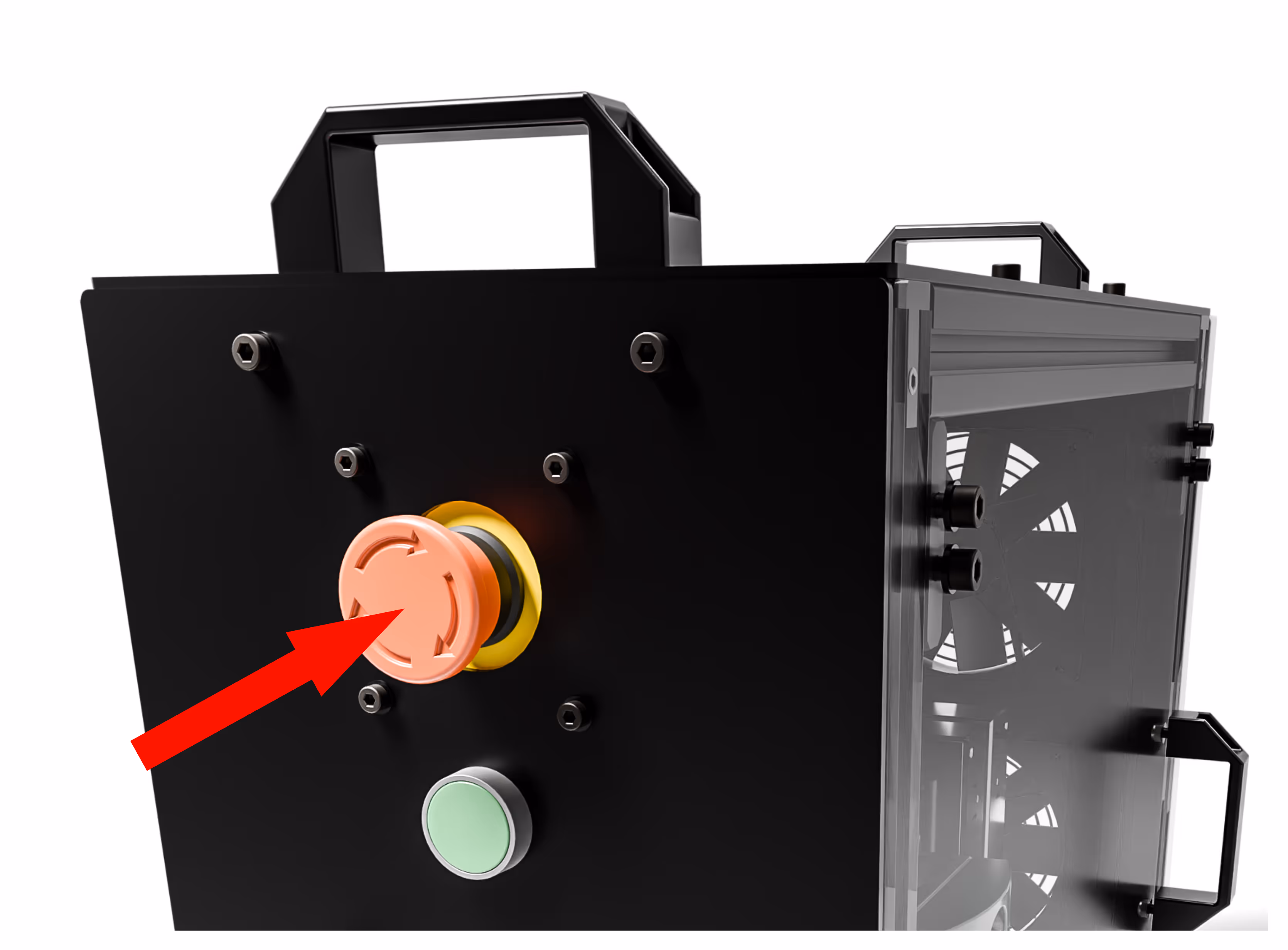
2) Releasing the E-stop: Rotate the E-stop button clockwise to release it.
3) Starting the Machine: Press the start button. You should hear a distinct "clack" sound, which indicates the contactor is engaging. This is normal.
4) Powering On: The Rodent and VFD (Variable Frequency Drive) should power on. Note that the VFD may take a few seconds to fully activate.
5) Testing the E-stop: Once both the VFD and Rodent are powered on, press the E-stop button. This should turn them off. It is normal for the VFD to take a few seconds to power down, especially when the spindle is not in motion.
Before beginning operation, it is essential to verify that the E-stop (Emergency Stop) circuit is functioning correctly as intended.
Endstop check
Rodent - FluidNC (UCCNC instructions are below)
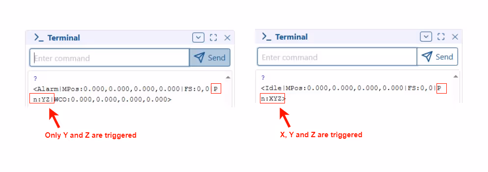
1. Type "?" in the console; the output should be similar to this: "Pn: ". (no triggered endstops)
2. Place a metal object in front of one of the endstops, ensuring the red light turns off.
3. Type "?" in the console again; the output should now display: "Pn: X ". (X axis is triggered). The last part of the output indicates which endstops are triggered.
4. Repeat step 3 with one endstop covered at a time, ensuring all endstops trigger correctly.If an endstop does not trigger, there may be a wiring issue.
5. If the LED on the endstop does not light up, it indicates that the endstop is not receiving power—check that both VCC and GND wires are properly connected. If the LED is functioning but the firmware does not register the endstop's activation, it likely means the GND and SIG wires are swapped. Refer to the wiring diagram for further clarification.
6. If the Y endstop is triggered but the firmware reports X or Z as being triggered, this indicates that the endstops are swapped on the control board. Check and correct the connections on the Rodent if necessary.
AXBB with UCCNC
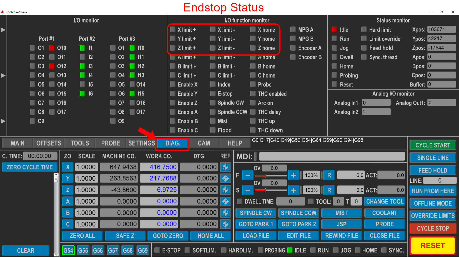
1. If you are using UCCNC, navigate to "DIAG." and check the endstop status on the I/O function monitor:
Home sequence
1. Home the machine and verify that all axes move towards their respective endstops.
2. Stay near the emergency stop button in case any endstop is misaligned and fails to trigger. This is a recommended safety practice for any CNC machine. While the hardware can generally be trusted, it is important to remain prepared for any unexpected issues during the commissioning phase.
Axes directions
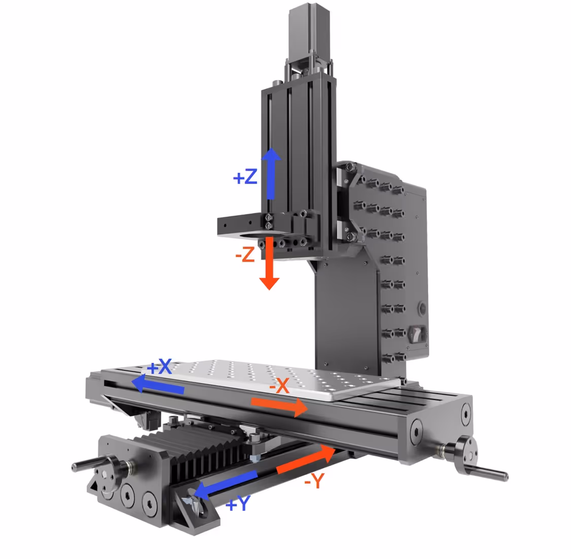
1. Select the desired distance and adjust the movement of each axis in small increments.

2. The movements should follow the directions indicated in the image below.
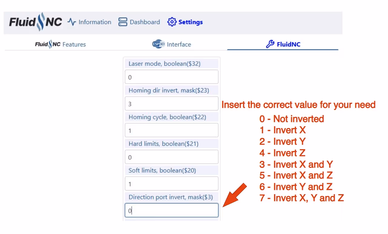
3.1 FluidNC If any of the axes are inverted, insert the apropriate value in the "Direction port inverter, mask" Under the FluidNC settings page:
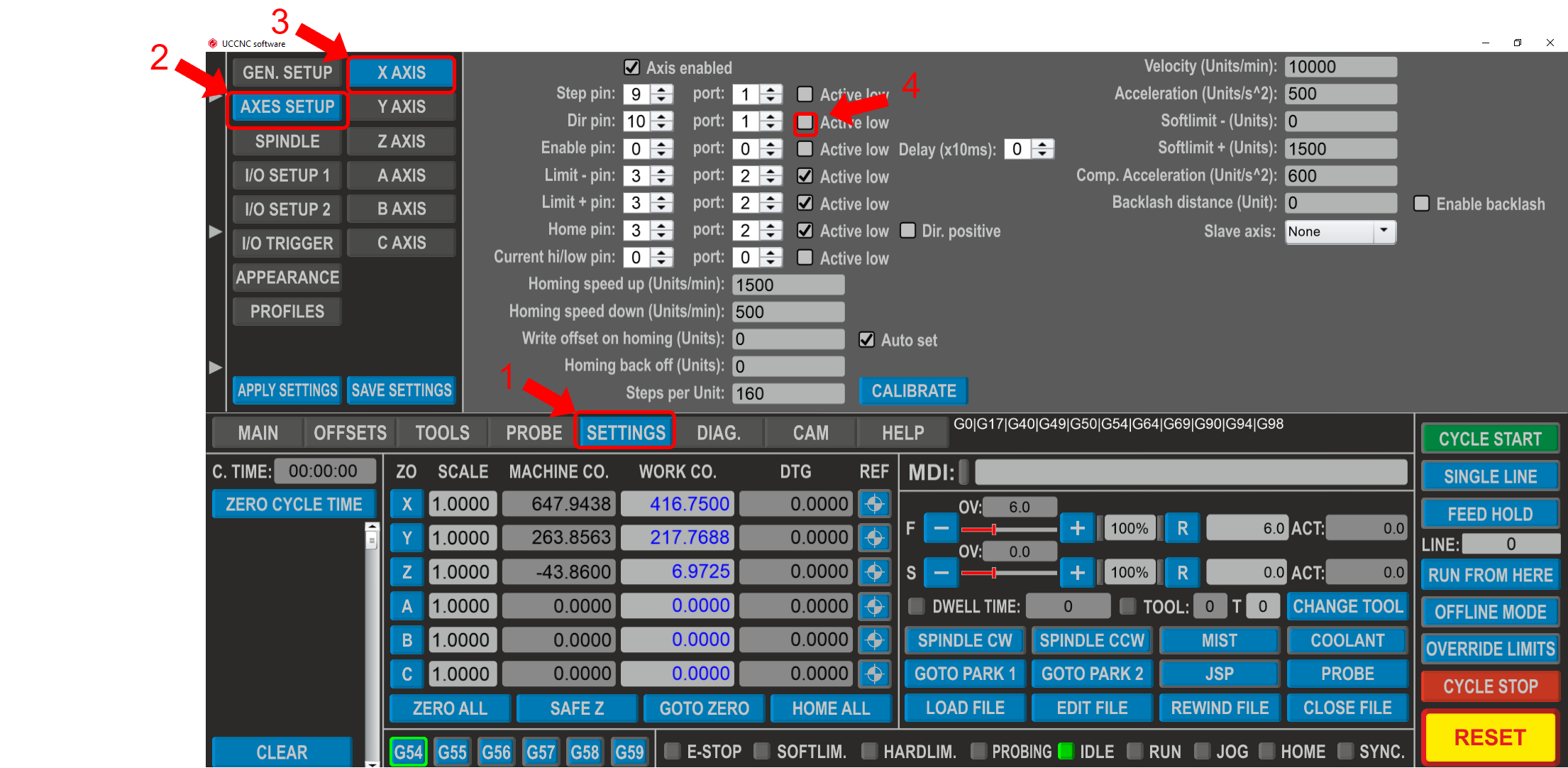
3.2 UCCNC Go to the "SETTINGS" (1) tab, then select "AXES SETUP" (2). Choose the desired axis (3) and enable or disable the checkbox (4) to invert the axis movement.
Calibration
Square and tram the machine
This step is not mandatory; however, it ensures dimensional accuracy and significantly enhances the quality of the finished part. A dial indicator is required for the next steps, and it is an essential tool for every machinist.
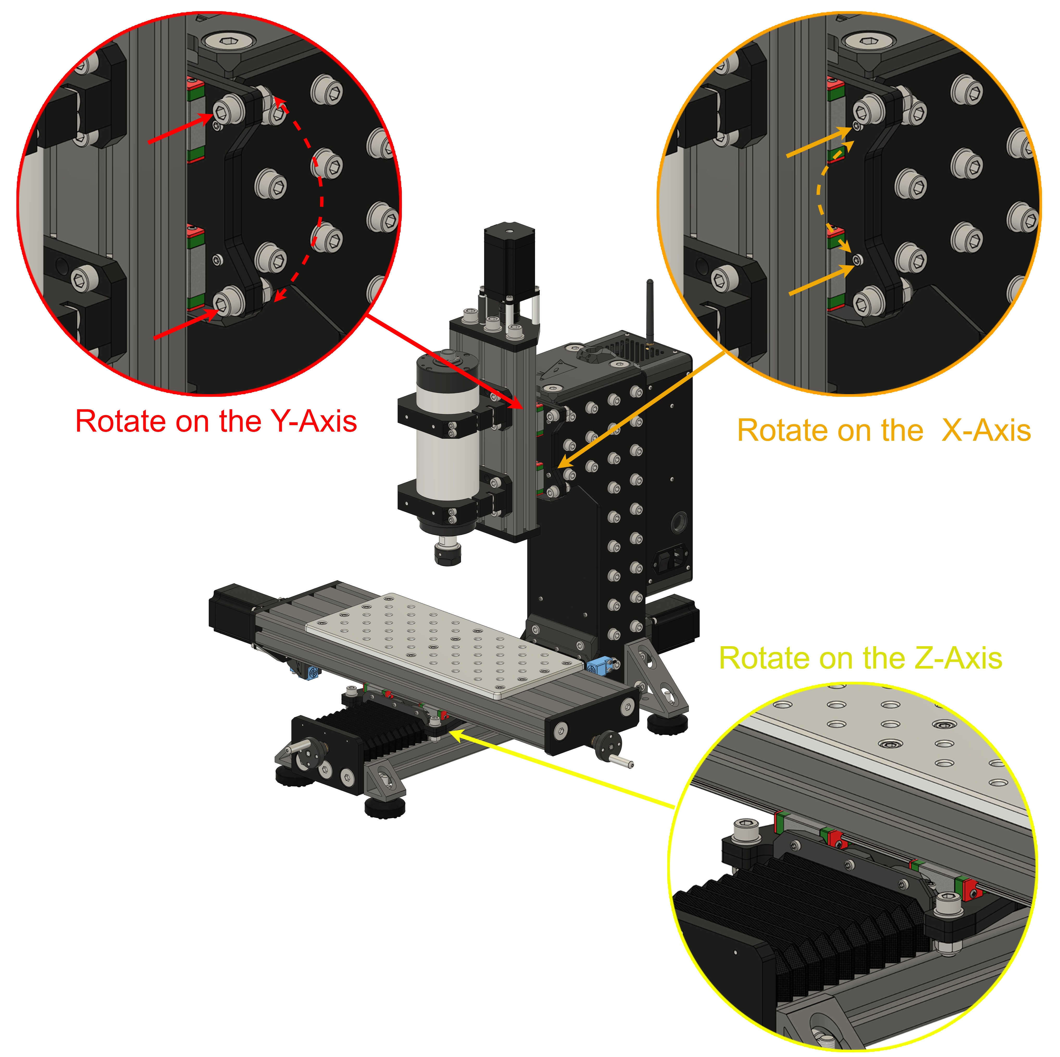
The Rat Rig Mill offers multiple adjustment points, allowing for near-perfect alignment without the need for disassembly or shimming. There are three primary adjustment points to tram and square each axis:
1) Squaring the XY Axis:
The XY joiner plates allow for easy squaring of the XY axis. By loosening the four screws, you can rotate the X-axis around the Z-axis, as shown in the image.
2) Tramming the Spindle Around the X-Axis:
Use the four M6 set screws on the plate to adjust the spindle alignment around the X-axis. Before making adjustments, slightly loosen the M8 screws that hold the two Z joiner plates together.
3) Tramming and Squaring the Z-Axis:
The Z-axis can be aligned by adjusting the four M8 screws on the Z joiner plate. Loosening these screws allows you to rotate the spindle around the Y-axis.
Additionally, we recommend watching this video for a better understanding of why tramming and squaring a mill is essential. "I'm No Expert, But" has an excellent video demonstrating the process on his own machine.
VFD config
In this step, we will configure the VFD. The spindle must be off to allow the VFD to be configured.
1. Start by ensuring the VI jumper is set currently in the VFD.
2. To navigate the VFD programs, click the “PRGN”(1) then arrow up or down to navigate the digits PD0YX(2), to change the second digit, click the “>>> SHIFT”(3) button, then use the arrows up and down to change this digit.
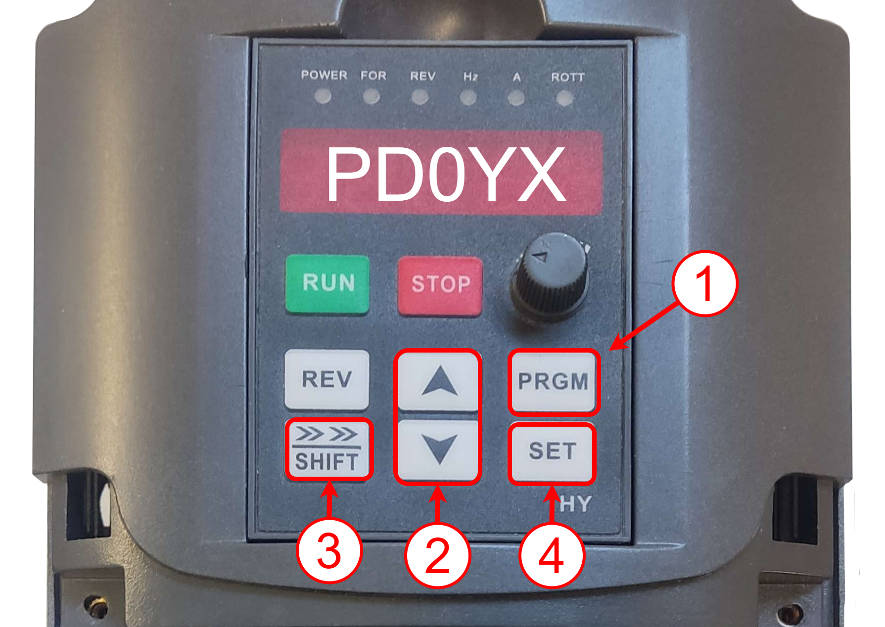
3. Use the same process to change the third digit.Navigate to PD013 and click “SET” (4), change the number to 8 and click “SET” again. This resets the VFD, ensuring we start with a clear sheet.
4. Navigate to PD001 and set it to 1, this allows the VDF to be controlled by the mainboard (Rodent or AXBB).
5. Navigate to PD002 and set it to 1.
6. Navigate to PD004 and set it to 400.
7. Navigate to PD005 and set it to 400.
8. Navigate to PD024 and set it to 1, this sets the STOP key as valid.
9. Navigate to PD052 and set it to 1, this enables the FA relay output to turn on the water pump whenever the spindle is on.
10. Navigate to PD070 and set it to 1 (for the Rodent controller), this sets the PWM signal to 0-5V, and set it to 0 (for the AXBB-E controller), setting the PWM signal to 0-10V. (AXBB-E, check if the pwm jumper is placed on the 10V setting).
11. Navigate to PD072 and set it to 400.
12. Navigate to PD144 and set it to 3000.
spindle calibration
In this step, we will check if the spindle rotates in the right direction and at the right speed.
1. Ensure the machine is in a safe position to turn on the spindle. Check if there aren’t any objects that might be hit by it, if you have the collet installed, remove it as it might become loose and fly off.
2. Run M3 S10000, the spindle should start spinning. Run M3 S0 and check if the spindle is decelerating clockwise. This is the “FOR” (forward) rotation direction.
3. If the spindle is rotating counterclockwise, you will need to swap two phases on the VFD connections, swap “U” with “V” for example and repeat step 2. The spindle should now spin in the opposite direction. If the spindle doesn’t rotate at all and makes a lot of noise like it is rotating on the inside, it means you have one of the phases swapped with the earth wire.
4. Run the command M3 S20000 and observe the display reading on the VFD. It should show a value very close to 20,000 RPM, with an error margin of up to 200 RPM being acceptable. If the VFD displays a value significantly higher or lower than 20,000 RPM, you will need to adjust the blue potentiometer behind the PWM screw terminals. Make small, gradual adjustments to the potentiometer until the display shows 20,000 RPM, with a tolerance of +/- 200 RPM.
5. Run the command M3 S6000 to verify if the spindle is close to the desired 6,000 RPM. Repeat the process for 24,000 RPM and check the spindle speed. The pre-configured spindle speed map should provide highly accurate values once the Rodent potentiometer has been properly calibrated.
6. During storage and shipping, the grease may settle in areas where it is not as needed, so running the spindle helps ensure proper lubrication where it is most required. Activate the spindle at 6000 RPM for 30 minutes to allow the grease to properly distribute to the bearings. Afterward, increase the rotation speed by 5000 RPM every 20 minutes to further enhance the spindle's lifespan.
CAM - Fusion360
In this step, we will configure the machine setup, post processor, and tool library.
Download the machine setup, post processor and tools library below:
- Machine setup
- Post Processor
- Tools library
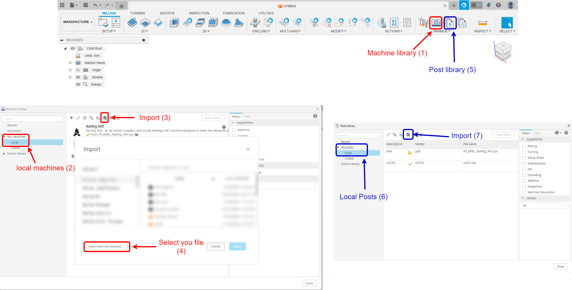
1. Open your Fusion 360 Manufacturing workspace. Navigate to "Machine Library" (1), select "Local" (2), and click "Import" (3). Then, click "Select your file" (4), choose the downloaded machine file, and store it in a known location.
2. To import the Post Processor, go to "Post Library" (5), select "Local" (6), and click "Import" (7). Then, choose the Post Processor folder from your computer.
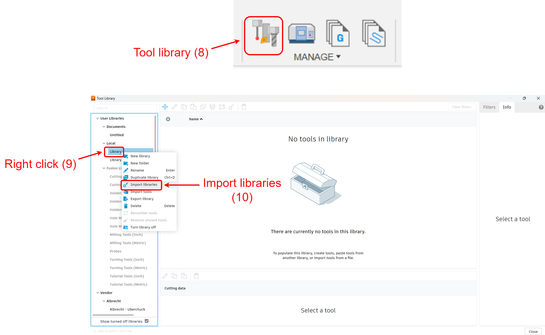
3. To import the Rat Rig tools library, click on the "Tool library" (8) and right click on the library option (9) and lastly select the "Import libraries" (10). Navigate your computer files and select the previously downloaded tools.