V-Core 4.0 - IDEX
calibration

| set-up
- Install the flex plate.
- Run the following command in your console:
BEACON_RATOS_CALIBRATEERROR. "Probe sample exceed sample_tolerance"
If you encounter the message ‘probe sample exceeded sample_tolerance’ during Beacon calibration, don’t worry! Here are a few potential fixes for the issue:
- Loose noozle. Hot tighten the noozle as mentioned here.
- Ensure the toolhead has no excessive play. Try gently rotating it to check for any loose screws on the rail or carriage plate.
- Verify that the beacon is securely attached.
- Verify that the Z arm screws are secure and sturdy.
- Ensure that the Z stepper motor couplers are tightly secured.
This issue usually comes down to assembly problems. If none of the above suggestions resolved it, triple-check your machine, something might be loose.
02. Belt Tension and Gantry Alignment
- You verified during assembly that the gantry moved freely without the belts, and is aligned correctly.
- All belts have been fitted with enough tension to allow the motion system to work.
- The previous chapter "Sanity Check" has been completed successfully.
- Home all axes on the machine by clicking "HOME ALL"
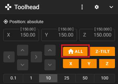
- Now let’s position the gantry to start the process. Insert 272mm in the Y axis position
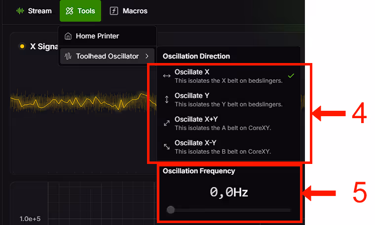
- Put your machine into IDEX COPY mode - IDEX Machines only

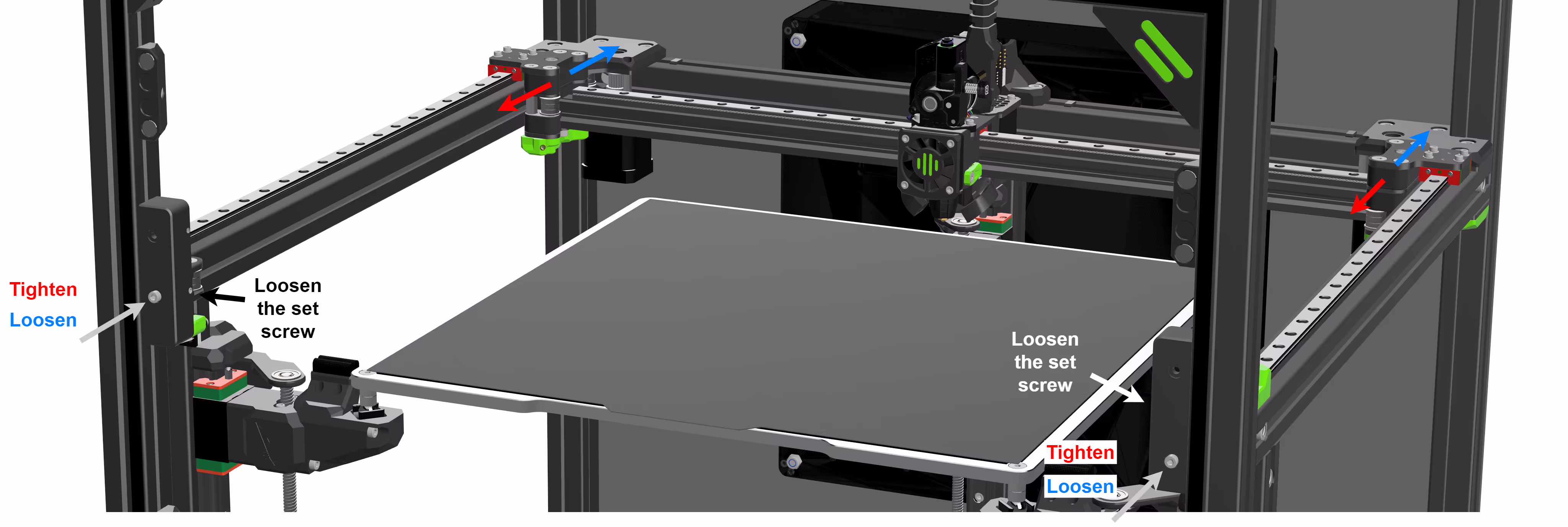
- Slightly loosen the screws highlighted in the image (the ones securing the 2020 aluminum extrusion)
- Run the following command in your console:
M18 - Please download and install the Smart Belt Drive app from the App Store or Google Play Store.Note!We suggest this app but you are free to choose another one. The most important thing is that the frequencies that you are measuring are right. So be aware that this is crucial and it will impact your machine performance.
- Open the “Frequency Measure”
- Click the red button to start recording the frequency.
- It's time to pluck your belt!Note - How to pluck:- Use your fingertip, fingernail, or a thin pick to pull the belt slightly outward and release it quickly.
- Do it perpendicular to the belt (like plucking a guitar string).
- Always pluck in the same spot, right in the middle of the belt section where you’re performing the pluck.
- Make the pluck quick and consistent, don’t press or dampen the belt vibration afterwards
- Repeat 3–5 times in the same spot with the same strength.
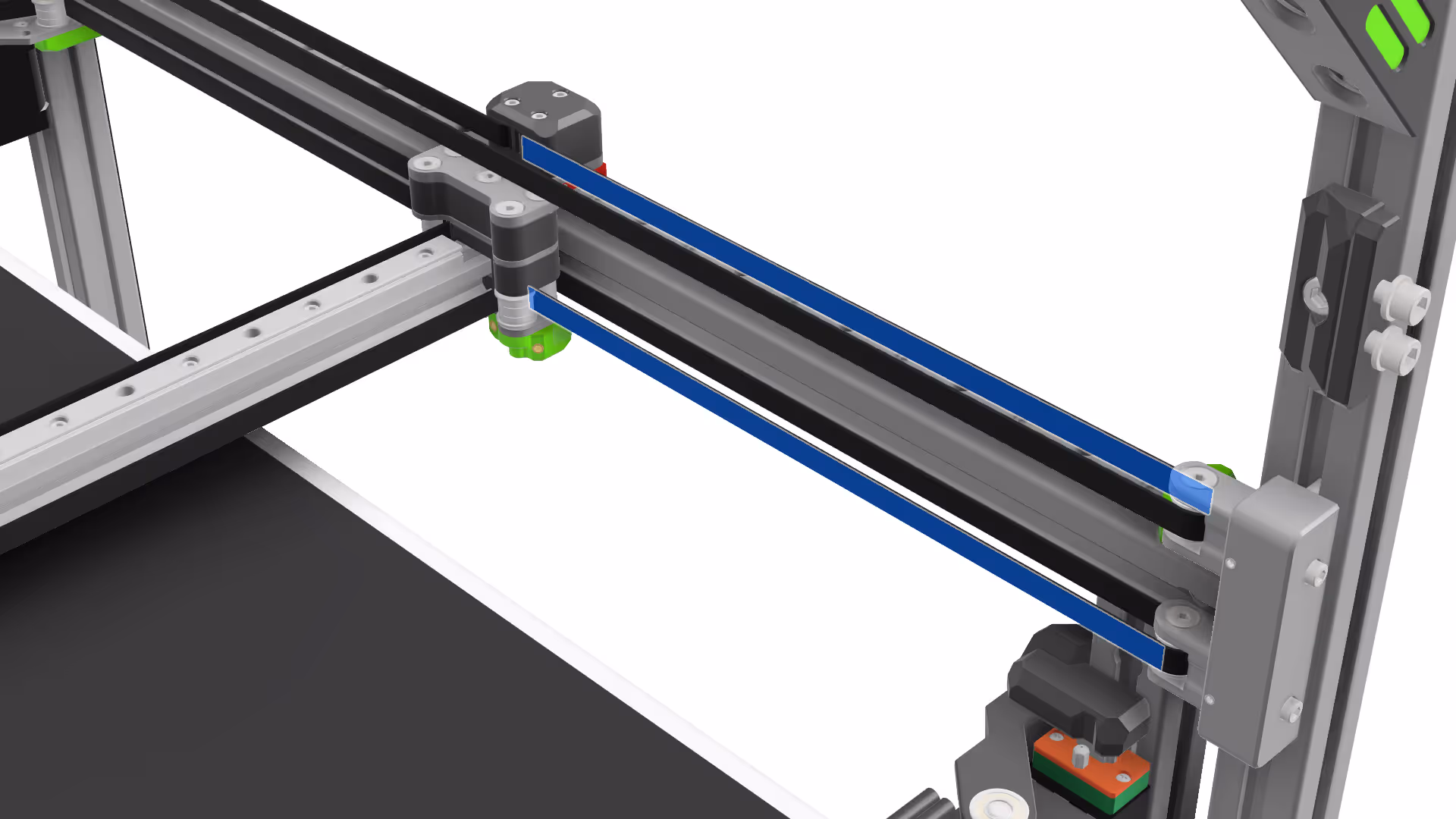
- Notice the belts that are highlighted — these are the ones you’ll need to pluck, on both sides of the machine.
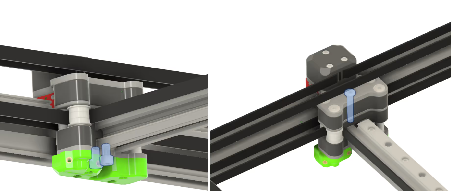
 Note - How to adjust tension::
- Whenever frequency values are higher than desired, turn the tensioner block screw anti-clockwise (as a rule of thumb, a quarter turn corresponds to roughly a 10 Hz adjustment).
If the values are below the desired level, turn the screw clockwise.
Remember to loosen the set screw on the side of the block.
Important Note:
Your Left and Right Belt needs to have the same frequency values.
If you are getting frequency readings around ~30 Hz or ~130 Hz, you need to repeat the plucks, those frequencies correspond to an incorrect harmonic. Make sure you obtain at least three consistent frequency readings. - Tension the Hybrid belts, aiming for 84 Hz (+-1Hz)
- Tension the CoreXY belts, aiming for 87 Hz (+- 1Hz)
- Because adjusting the CoreXY tension can affect the Hybrid tension, we need to check the Hybrid tension again. Repeat steps 10 and 11 until all the belts are plucking with the correct frequency.
- Now that you’ve tensioned the belts and reached the desired frequency, we’ll proceed with the fine adjustment.
- Move the toolhead(s) to the center of the machine (they must be clear of the motor cages and any PTFE tube guides). - Gently slide the gantry fully to the back until the joiners contact the stepper motor cages.
- Press both joiners against the stepper motor cages. You will probably feel that one side is making firm contact, and the other has some play. We need to adjust the balance of corexy belt tension until both sides are making firm contact at the same time with no play.
If both sides are making firm contact, no further adjustment is required.
Otherwise, identify the side that does not make firm contact. - Loosen only the lower set screws on both the left and right tensioner blocks.Note - Explanation Block:
We will need to slightly decrease the tension on the identified side by turning the tension screw anti-clockwise, and slightly increase the tension on the other side by turning the screw clockwise.
To avoid causing excessive gantry twist, make any adjustments symmetrically on both sides but in opposite directions.
For example, if you tighten the right tensioner, slightly loosen the left tensioner. Do not attempt to straighten the gantry using only one side. - Make small adjustments until both joiners make firm contact with the stepper motor cages at the same time.
- Tighten the gantry screws that were slightly loosened in step 5.
03. Belt tension - Advanced users only
Belt tension graphs are meant to help diagnose your machine assembly rather than serve as a tuning tool. It’s easy to over-focus on them, but they should be seen as a guide for spotting issues rather than a perfect benchmark. Belt tension analysis is a nuanced and evolving subject; for deeper exploration, check out the excellent work by the Klippain Shaketune team.
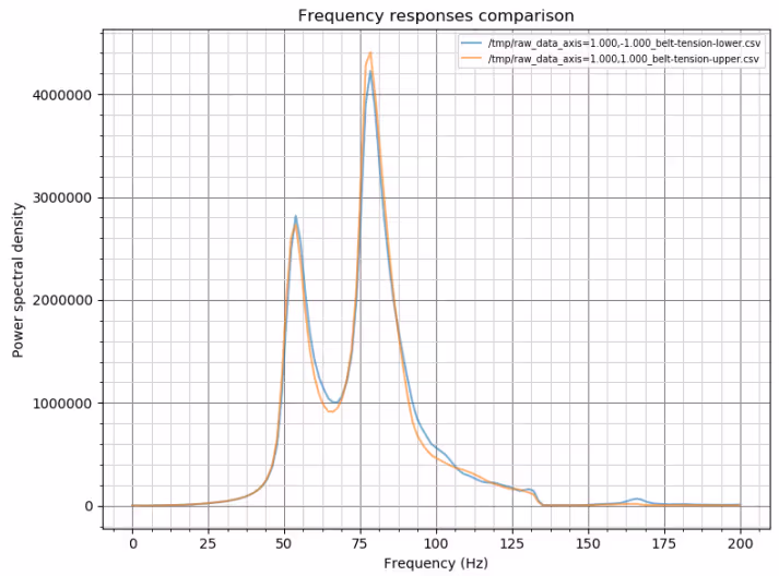

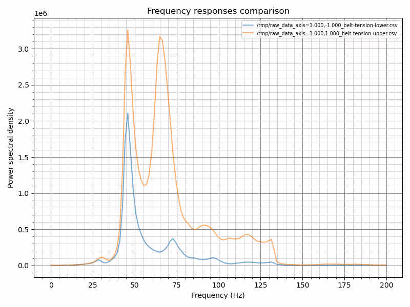
- The two peaks (blue and orange) must be aligned on the same frequency, if they are not vertically aligned, then you need to tension or loosen the belts, and your gantry is most likely twisted. Refer to this guide to help you troubleshoot.
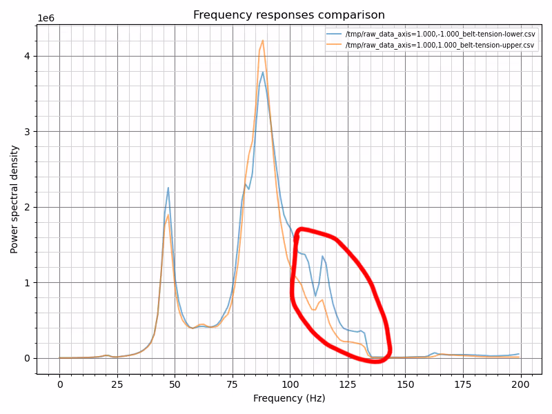
- Toolhead vibrations typically appear in the 100–150 Hz range and can result from loose screws, damaged printed parts, unsecured wires, or insufficient cable management (e.g., missing zip ties).
- There is an issue with the belt path: If your graph lacks one or two peaks. It likely means a belt is rubbing against something along its path, such as an idler, motor pulley, or the frame.3.1. In the example below, only one belt path is affected.
 3.2. In the example below, both belt paths are affected.
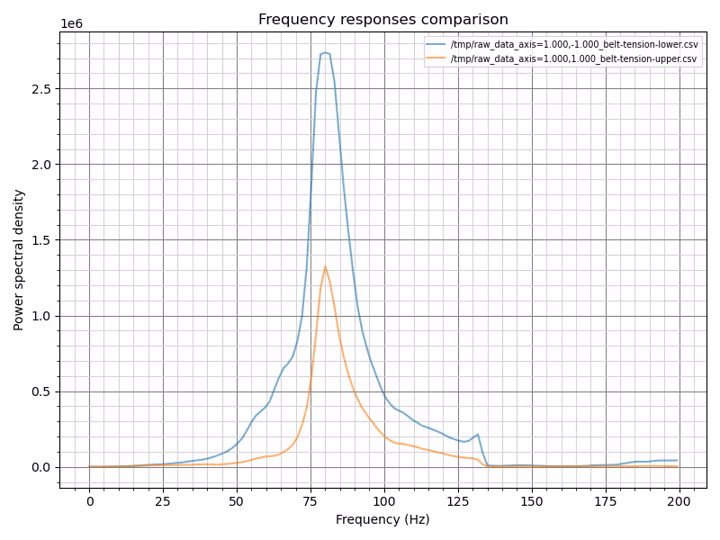
- Lastly, it’s important to distinguish between vibrations and swinging.4.1. Vibrations appear as zig-zag patterns on the graph and are usually caused by loose screws on the toolhead or gantry. Loose idler stacks or missing shims can produce the same effect. Carefully inspect the assembly to identify and correct the source.
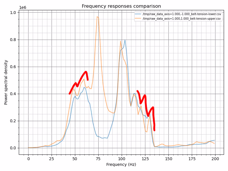 4.2. Swinging appears as smooth curves on the graph and is often caused by the printer resting on an unstable table or uneven floor. Ensure your machine is on a solid, level surface to prevent it from shaking.
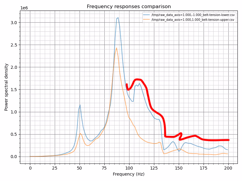
04. Input ShapER
- Open the SCRIPTS window and click GENERATE SHAPER GRAPHS.

- After completion, open the machine tab (1) and navigate to the input_shaper folder.
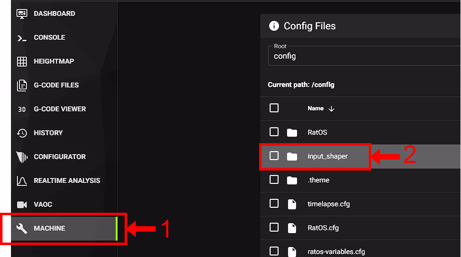 Note!You will find four files. Each file name indicates the toolhead (T0 or T1), the axis (X or Y), and the timestamp. Example:
T0_resonances_y_2025-02-17-163419represents a T0 Y-axis input shaper graph created at 16:34:19 on February 17, 2025. Graph Information below.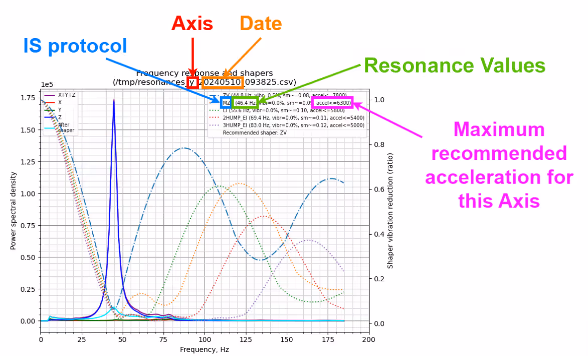
- Open the Dashboard tab and enable IDEX COPY mode in the IDEX window.
- Click GENERATE SHAPER GRAPHS again
- Enable IDEX MIRROR mode in the IDEX window.

- Click GENERATE SHAPER GRAPHS again
- Open the input_shaper folder. You should now see twelve graphs.
Standard: T0X, T0Y, T1X, T1Y
Copy mode: T0X_COPY, T0Y_COPY, T1X_COPY, T1Y_COPY
Mirror mode: T0X_MIRROR, T0Y_MIRROR, T1X_MIRROR, T1Y_MIRROR - Open every graph and note down the MZV resonance frequencies and the graph they are from.
- Open the machine (1) tab and then open the printer.cfg (2) file.

- Copy the code below and paste it inside your printer.cfg. Replace the graph names with the corresponding MZV resonance frequencies you previously recorded in step 8.
[gcode_macro RatOS] variable_shaper_x_freq: [T0_X, T1_X, COPY_X_AVERAGE, MIRROR_X_AVERAGE] variable_shaper_y_freq: [T0_Y, T1_Y, COPY_Y_AVERAGE, MIRROR_Y_AVERAGE] variable_shaper_x_type: ["mzv", "mzv", "mzv", "mzv"] variable_shaper_y_type: ["mzv", "mzv", "mzv", "mzv"]Note!To calculate the average value for Copy mode, add the resonance frequencies of T0 and T1 in Copy mode and use the resulting average as the COPY_X_AVERAGE and COPY_Y_AVERAGE.
For Mirror mode, perform the same calculation using the T0 and T1 Mirror mode graphs to obtain the MIRROR_X_AVERAGE and MIRROR_Y_AVERAGE values. - Click "SAVE & RESTART" at the top right of the printer.cfg page
05. Resonance analysis
Discover how this diagnostic tool works and how you can apply it
If the incorrect toolhead moved, it means the X stepper and DC stepper connectors on the Octopus board are swapped. Disconnect the machine from power and swap the connectors. Check the wiring diagram here.
06. Initial vaoc calibration
🛈 Learn more about the endstop calibration

- Press Home All (1) and then click on Z-Tilt (2)

- Run the following command in your console
_VAOC_RESET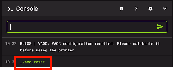
- Disable the steppers by running the following code in your console
M84 - Navigate to the VAOC tab, and hit start calibration.

🛈 MOVE OUT OF RANGE - ERROR when using VAOC
🛈 VAOC Camera freezing. HELP!
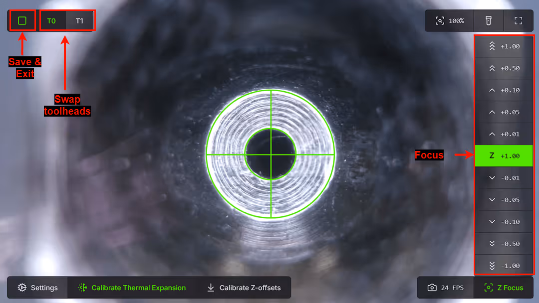
Note!T0 is automatically selected as the main toolhead, we advise flipping the camera movement right away, this makes adjustment easier, but it’s a personal preference. Measure the external diameter of your nozzle with a set of calipers, the standard phaetus nozzle is 1 mm, insert the value in the settings window. Adjust the pixel rate so the nozzle hole matches the crosser size.
- Adjust the Z position on the right side to achieve a clear focus on the nozzle. Then, drag the nozzle hole to the center of the crosshair.
🛈 Can't focus both nozzles. HELP!
- Adjust the Z position on the right side to achieve a clear focus on the nozzle. Then, drag the nozzle hole to the center of the crosshair.
- Switch between T0 and T1 two to three times to achieve perfect nozzle alignment. Align between each verification if necessary.Note!A slight drift between nozzles is normal during the first few attempts. Repeat the switching process until both nozzles remain aligned.
- Once you are satisfied with the nozzle alignment, click the square icon at the top left corner to save and exit to end the VAOC procedure.
- Run the following command in the console:
CALCULATE_DC_ENDSTOP
- Copy the output text from the console and paste it at the bottom of your printer.cfg file.


- Run the following command in the console:
_VAOC_RESET - Perform a new VAOC nozzle alignment procedure by repeating steps 4, 5, 6, and 7.Important Note!Validate the calibration:
Open the ratos-variables.cfg file inside the machine tab and check the idex_xoffset value, if the value is higher than 1.0mm or lower than -1.0mm then the printer suffers from mechanical issues like a skewed gantry and/or uneven belt tensioning or belt length.

Z endstop check and calibration
Both nozzles should be at the same height. This is impossible to achieve in real life, due to machining tolerances and assembly variances. Getting them as close together as possible is mandatory to ensure the best idex experience and allow for the usage of copy and mirror mode.
- Press Home All (1) and then click on Z-Tilt (2)
- Navigate to the VAOC tab, and hit start calibration.
- Calibrate the XY offsets for T0 by dragging the nozzle into the center of the crosshair
- Switch to T1 and Calibrate the XY offsets by dragging the nozzle into the center of the crosshair
- Switch between T0 and T1 two to three times to achieve perfect nozzle alignment. Align between each verification if necessary.
- Then click Calibrate Z-Offset.

- Click the square icon at the top left corner to end the VAOC.
- Open the machine console and observe the Z_offset value between T0 and T1. This value should be smaller than 0.07 mm.

🛈 Improve your Z offset
There are some ways to achieve a smaller Z offset
PRO TIP: If your value is larger than this, you need to check if both toolhead are correctly assembled, and everything is tighten down. Please go back to step 1 and redo the testing, check if the values from different tests are consistent.
- If the values are not consistent, it would mean there is a mechanical problem, like a loose nozzle, loose heartbreak screws, loose lead screw coupler, poorly assembled VAOC module and Z endstop, loose toolhead or hotend, etc…
- If the values are consistent, then you need to figure out which nozzle is the highest. If the Z_offset value is positive, it means that T0 is lower than T1. If the Z_offset value is negative it means that T1 is lower than T0.
- The easiest fix is trying to loosen and retighten both nozzles.
If this doesn’t work, you can try to lower the highest nozzle, by using a small shim in between the hotend and the toolhead plate. The small plate that holds the electrical crimps together is generally 0.2mm thick, if you have any available from your kit or toolboard kit, you may use it for this purpose, make sure to measure it before with a good set of calipers (This comes at a cost of lost mechanical strenght, this methos is only as a last resource).
The goal is to achieve a Z_offset lower than 0.05mm, it’s impossible to achieve a perfect Z_offset so don’t overdo it.🛈 The Z endstop readings are unreliable. HELP!
If your Z-endstop readings are unreliable:
Unreliable Z endstop measurements can result from several factors.
Below are some potential causes and areas to inspect:
Toolhead-Related Issues:
If only one toolhead exhibits inconsistent readings, the following issues may be responsible:
1) A loose nozzle.
2) Accumulation of molten filament in the nozzle.
3) The Rapido hotend not being securely fastened to the mounting plate.
4) Loose screws on the MGN12C carriage.
Z Endstop Assembly Issues:
1) The POM insert may be damaged or excessively tight within the VAOC body, causing binding of the Chicago bolt.
2) The Chicago bolt itself may not be properly tightened.
Carefully inspect the Z endstop assembly to ensure all components are correctly installed and functioning as intended.
07. Skew Calibration
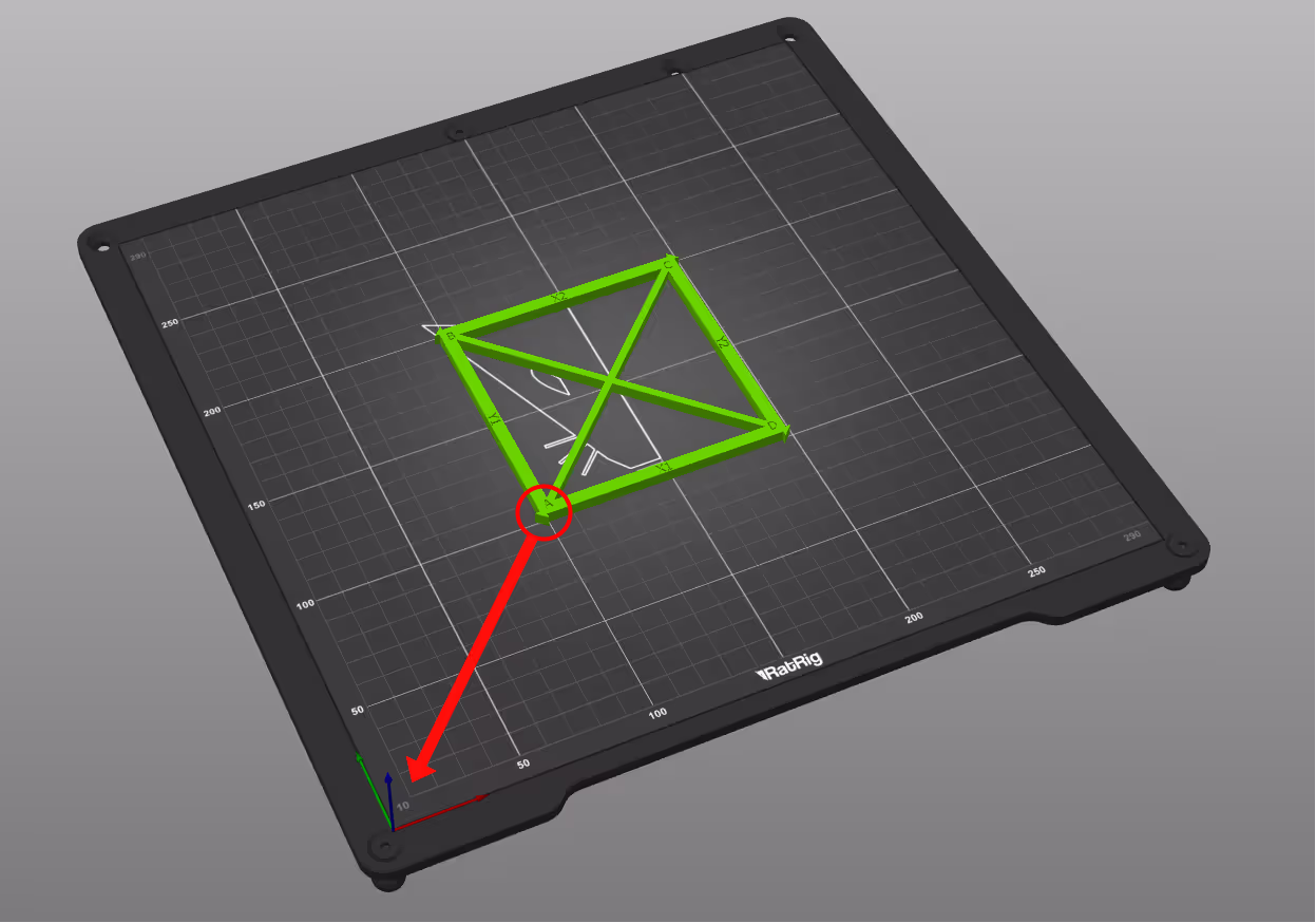
- Start by downloading the Skew_correction_tool.stl. Then open it inside your slicer. If this is your first time following this guide, please follow the Slicer installation first, then get back to this step.
Caution.
When slicing the model, make sure the A corner is pointing to the origin of the print area.
- Guarantee that no skew correction is running on your machine, check that variable_skew_profile is commented out in the macro configuration section. or type the command below in the terminal. For more information, click here.
SET_SKEW CLEAR=1The [skew_correcton] module requires 3 measurements; the length from Corner A to Corner C, the length from Corner B to Corner D, and the length from Corner A to Corner D.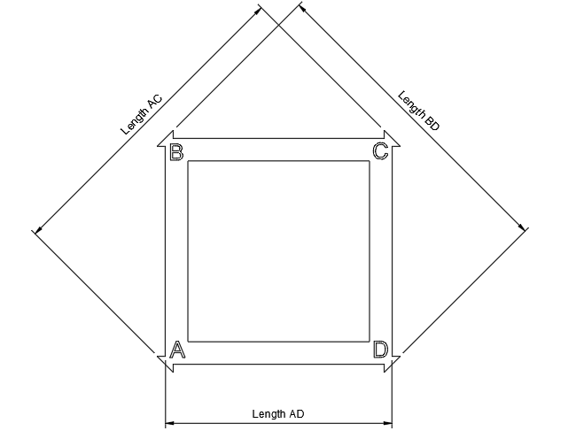 Let's take the following measurements as an example:
AC= 141.15mm
BD= 140.9mm
AD= 99.65mm - Go into the printer.cfg and add the following lines:
[gcode_macro RatOS] variable_skew_profile: "my_skew" - Click “SAVE AND RESTART” at the top right of the printer.cfg window, then run the following command in your console:NOTE: Replace the "AC, BD, AD" text with your values.
SET_SKEW XY=AC,BD,ADNote!With the previous example, we have:
SET_SKEW XY=141.15,140.9,99.65 - Run the following command in your console
SKEW_PROFILE SAVE="my_skew" - Run the following command in your console
SAVE_CONFIG - Re-print the test, make sure AC=BD. If not, double check all measurements and start this calibration again.